Message Alert
Upload Multiple Part Numbers for Quotation
-
 Measuring Instru & tester
-
 Power Tool
-
 Industrial Accessories
-
 Safety Range
-
 Electrical
-
 Hand Tool
-
 Agriculture Equipment
- PULVERIZER
- HONDA
- AATOMIZE
- AMER
- ECO
- SHAKTI
- SUNTEC
- KIRLOSKAR
- AGRIPLAST
- SYDLER
- POLYSEAL
- PECO
- MASCHIO GASPARDO
- RAAJGAD
- SUKOON
- NEPTUNE
- TILLER
- AATOMIZE
- ECO
- SOIL CART
- LANCER
- KIRLOSKAR
- LORIYA
- KUBOTA
- NATIONAL AGRO
- ROHITKRISHI
- TK AGRO
- LEMKEN
- SWAN AGRO
- JAGATJIT
- GILL
- KS
- SOILTECH
- SUKOON
- UMIYA
- APL
- NEPTUNE
- VST SHAKTI
-
 Electronic Component
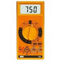
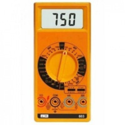
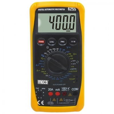
MECO Digital Multimeter MODEL 603 3½ Digit 2,000 Count LCD 17mm Large LCD, Audiable Continuty, Diode & hFE Testmodel
- Available
BULK ORDER REQUEST FORM
MECO Digital Multimeter MODEL 603 3½ Digit 2,000 Count LCD 17mm Large LCD, Audiable Continuty, Diode & hFE Testmodel
Be A Seller
Apply NowEXPERIENCE ZILLIONS BUYERS APP ON MOBILE
DC Voltage: 200mV/2/20/200/1000V
Accuracy ±(0.5%rdg+1dgt) on all ranges
AC Voltage: 200mV/2/20/200/750V (50-500Hz)
Accuracy ±(1%rdg+4dgt) on all ranges except ±(1.5%rdg+4dgt) on 750V
DC Current: 200mA/2mA/20mA/ 200mA/20A Accuracy ±(1%rdg+1dgt) on all ranges except ±(2%rdg+3dgt) on 20A
AC Current: 200mA/2mA/20mA/ 200mA/20A (50-500Hz) Accuracy ±(1.2%rdg+4dgt) on all ranges except ±(2%rdg+4dgt) on20A
Resistance: 200V/2kV/20kV/200kV/ 2000kV/20MV200MV Accuracy ±(0.8%rdg+1dgt) on all ranges, except ±(1%rdg+3dgt) on 200V ±(3%rdg+3dgt) on 20MV ±(5%rdg+10dgt) on 200MV Sp.
Function Audible Continuity, Diode Check, hFE Test Power One 9V
Battery Battery Life :200 hours typical
Dimensions 170 x 80 x 43mm (approx.) Weight 240gms Including Battery (approx.)
Low Battery " " is indicated + Accessories Supplied with Pair of Test Leads, Carrying Case, Battery (installed), Instruction Manual and Spare Fuse
| How to use and operation | 2.1 VOLTAGE MEASUREMENT: 1. Connect red test lead to “V-V”input terminal and black test lead to “COM” input terminal. 2. Set Function/Range switch to desired voltage type (DC or AC) and range. If magnitude of voltage is not known, set switch to the highest range and reduce until a satisfactory reading is obtained. 3. Turn off power to the device or circuit being tested and discharge all capacitors. 4. Connect test leads to the device or circuit being measured. 5. Turn on power to the device or circuit being measured. Voltage value will appear on the digital display along with the voltage polarity. 6. Turn off power to the device or circuit being tested and discharge all capacitors prior to disconnecting test leads. 2.2 CURRENT MEASUREMENT 1. Connect red test lead to the “mA” input terminal for current measurements up to 200 milliamperes. Connect black lead to the COM input terminal.2. Set Function/Range switch to desired current type (DC or AC) and range. If magnitude of current is not known, set switch to the highest range and reduce until a satisfactory reading is obtained. 3. Turn off power to the device or circuit being tested and discharge all capacitors. 4. Open the circuit in which current is to be measured. Now securely connect test leads in series with the load in which current is to be measured. 5. Turn on power to the device or circuit being tested. 6. Read current value on digital display. 7. Turn off all power to the device or circuit being tested and discharge all capacitors. 8. Disconnect test leads from circuit and reconnect circuit that was being tested. 9. For current measurment of 200mA or greater, connect the red test lead to “20 A” input terminal & black test lest lead to the “COM” input terminal. If the resistance being measured is part of a circuit, turn off power to the circuit and discharge all capacitors. 2.3 RESISTANCE MEASUREMENTS 1. Connect red test lead to V-V input terminal and black test lead to COM input terminal. 2. Set Function/Range switch to desired V position. If magnitude of resistance is not known, set the switch to highest range and reduce until a satisfactory reading is obtained. 3. If the resistance being measured is part of a circuit, turn off power to the circuit and discharge all capacitors. 4. Connect test leads to the device or circuit being measured. When measuring high resistance, be sure not to contact adjacent points even if insulated, because some insulators have a relatively low insulation resistance, causing the measured resistance to be lower than the actual resistance. 5. Read resistance value on digital display. If a high resistance value is shunted by a large value of capacitance, allow digits to stabilize. NOTE A. All resistance ranges on the DMM, except the 200V and 200MV range, are low-power ohms. This allows accurate measurements of in-circuit resistance because the test voltage is below that is necessary to activate a diode junction B. The 200MV range has a fixed 10-count off set in its reading. When the test leads are shorted together in this range, the meter will display 010 in the 200MV range. This reading must be subtracted in order to obtain a true measurement. For example, when measuring a resistance of 100MV on the 200MV range, the display will read 110. 2.4 DIODE AND TRANSISTOR TEST MEASUREMENTS The special Diode Test Function allows relative measurements of forward voltage drops across diodes and transistor junctions. This function also permits measurement of in-circuit semiconductor junctions. 2.4.1 DIODE TESTS 1. Connect red test lead to V-V input terminal and black test lead to COM input terminal. 2. Set Function/Range switch to the diode test position. 3. If the semiconductor junction being measured is part of to a circuit, turn off power to the circuit and discharge all capacitors. 4. Connect test leads to the device. 5. Read forward voltage drop value on digital display. 6. If the digital display reads overrange (1) reverse the lead connections. The placement of the test leads when the forward reading is displayed indicates the orientation of the diode. The red lead is positive and the black lead is negative. if overrange (1) is displayed with both lead connections, the junction is open. If a low-reading (less than 1,000) is obtained with both lead connections, the junction is shorted internally or (if junction is measured in a circuit) the junction is shunted by a resistance less than 1KV. In the latter case the junction must be disconnected from the circuit in order to verify its operation. 2.4.2 TRANSISTOR JUNCTION TESTS 1. Bipolar transistors can be tested in the same manner as diode, junctions formed between the base and emitter and the base and collector of the transistor. Measurement between the collector and emitter also should be made to determine if a short is present. 2.5 TRANSISTOR hFE MEASUREMENTS 1. Transistor must be out of circuit. Set the function/range switch to the hFE position. 2. Plug the emitter, base and collector leads of the transistor into the correct holes in either the NPN or the PNP transistor test socket, whichever is appropriate for the transistor being checked. Read the hFE (beta, or DC current gain) in the display. 2.6 CONTINUITY MEASUREMENTS:
1. Set the selectors switch to the ))) position.
2. Continuity between probe tips will be indicated by an audible beep
when resistance is below 100V. |
| Maintenance | 3. MAINTENANCE 3.1 TROUBLESHOOTING If there appears to be a malfunction during the operation of the meter, the following steps should be performed in order to isolate the cause of the problem: 1. Check the battery. 2. Review the operating instructions for possible mistakes in operating procedure. 3. Inspect and test the Test Probes for a broken or intermittent connection. 4. Inspect and test the fuse. If it is necessary to replace the fuse, be sure to install one of the proper current rating. 3.2 BATTERY AND FUSE REPLACEMENT: To prevent electrical shock hazard, turn off the multimeter and any device or circuit under test and disconnect the test leads before removing the battery snap or the rear cover. BATTERY REPLACEMENT 1. Remove the battery cover screw, and slide the battery cover towards the bottom of the meter. 2. Remove and disconnect the old battery from the meter and replace with a new unit. Wind the excess lead length once around the battery clip. Install the battery and replace the battery cover. |
When calculating international shipping costs, Your total international shipping costs are influenced by your chosen trade route, and if it passes through a particular zone or channel, additional charges may apply. For more information on how your trade route impacts zone-specific charges, contact query@zillionsbuyer.com or +91-9168103909
If a buyer arranges an export delivery, the buyer must provide proof that the export is acceptable to the competenttax and customs authorities. All other shipments of Titled Products must pass through the Purchaser at an earlier date, when (i) the port from which the exported Product is released for export or (ii) the item leaves the territorial land, sea or airspace of the sending country.
Related Products